LNA NF auto test solution
Low noise amplifier is a typical electron device/circuit who usually operate at the first stage in the receiver architectures. According to the cascade noise formula, if the first stage could offer a large signal power/voltage gain, its intrinsic noise can dominate the over all noise figure of the whole receiving chain. Hence, an amplifier with low noise is quite critical to ensure the large dynamic range of a RF receiver.
RF noise can arise from a variety of sources, including thermal noise, shot noise, flicker noise, and other noise sources. The thermal noise arises due to the random motion of electrons, which is directly related to the temperature of the system. Shot noise is caused by the discrete nature of current flow in a conductor, while flicker noise is a low-frequency noise caused by the random trapping and de-trapping of charges in the device’s oxide layer. All of these sources of noise can contribute to the overall RF noise in the LNA, reducing the signal-to-noise ratio and ultimately leading to a degraded performance (large NF).
The Y-factor method is a widely used technique for measuring the noise figure (NF) of a device, which is a measure of the degradation of the signal-to-noise ratio caused by the device. The Y-factor method is based on the principle of measuring the power spectral density of the noise output from the Device Under Test (DUT) at two different conditions, typically the output noise power density with “hot” noise source $N^{\mathrm{ON}}$ and the output noise power density with “cold” noise source $N^{\mathrm{OFF}}$. The ratio of the two power density is the namely Y-factor, which could be written as:
$$Y = \frac{N^{\mathrm{ON}}}{N^{\mathrm{OFF}}}$$
In addition, the “hot” output $N^{\mathrm{ON}}$ can be expressed in two terms, which constituting the noise power of the DUT and the noise power of the noise source working in “hot” condition, namely:
$$N^{\mathrm{ON}}=GKT_s^{ON}B+GKT_eB$$
where the G is the intrinsic gain of the DUT, $T_s^{ON}$ the equivalent noise temperature of the “hot” state noise source, $T_e$ the equivalent noise temperature of the DUT, and B the bandwidth. In this method, we could also derive the expression of the off state output noise power as:
$$N^{\mathrm{OFF}}=GKT_s^{OFF}B+GKT_eB$$
Then, the Y factor can be transformed to :
$$Y=\frac{T_s^{ON}+T_e}{T_s^{OFF}+T_e}$$
Moreover, the equivalent noise temperature of DUT can be derived as:
$$T_e=\frac{T_s^{ON}-Y*T_s^{OFF}}{Y-1}$$
then, we could have the noise figure of DUT:
$$NF_{DUT}=1+\frac{T_e}{T_0}$$
where $T_0$ is the room temperature. The Y-factor method is a simple and effective way of measuring the NF, but it requires accurate temperature control and calibration, as well as a stable, low-noise reference source. The Y-factor method can also be affected by non-ideal behavior of the DUT, such as nonlinearity and spurious noise. To account for these effects, additional measurements and analysis may be necessary.
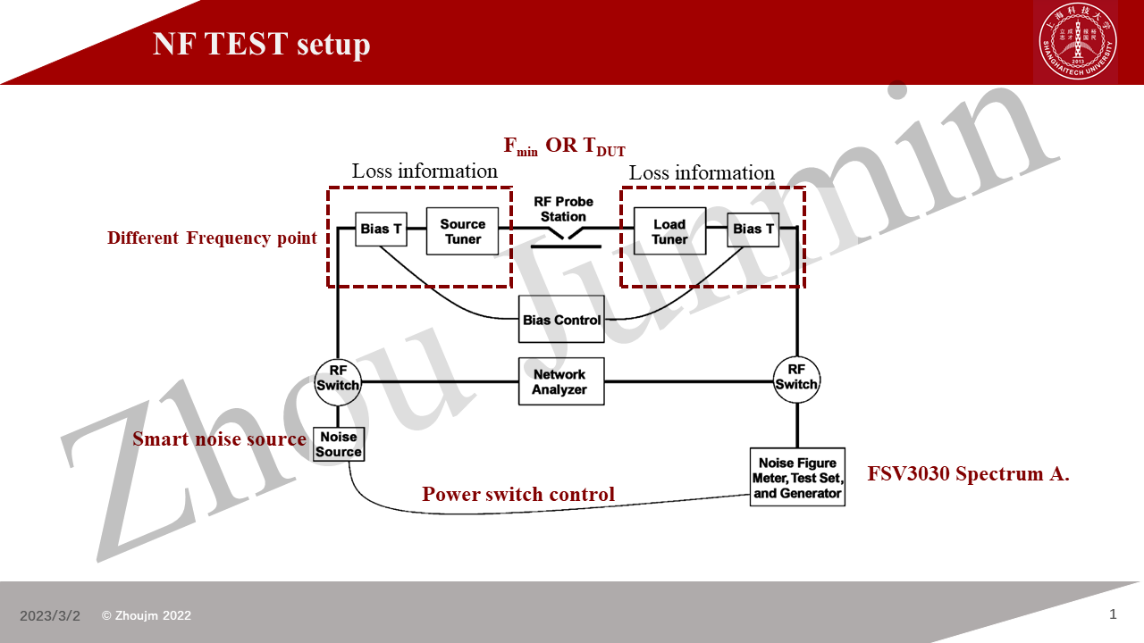
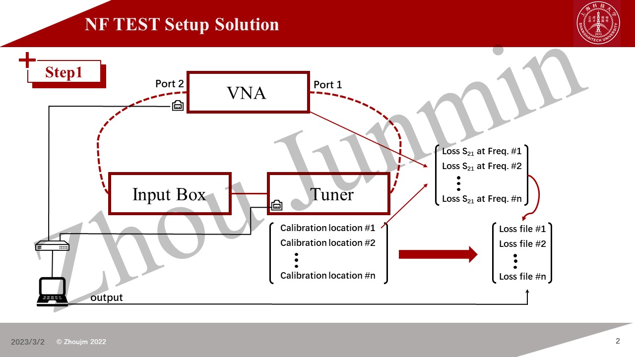
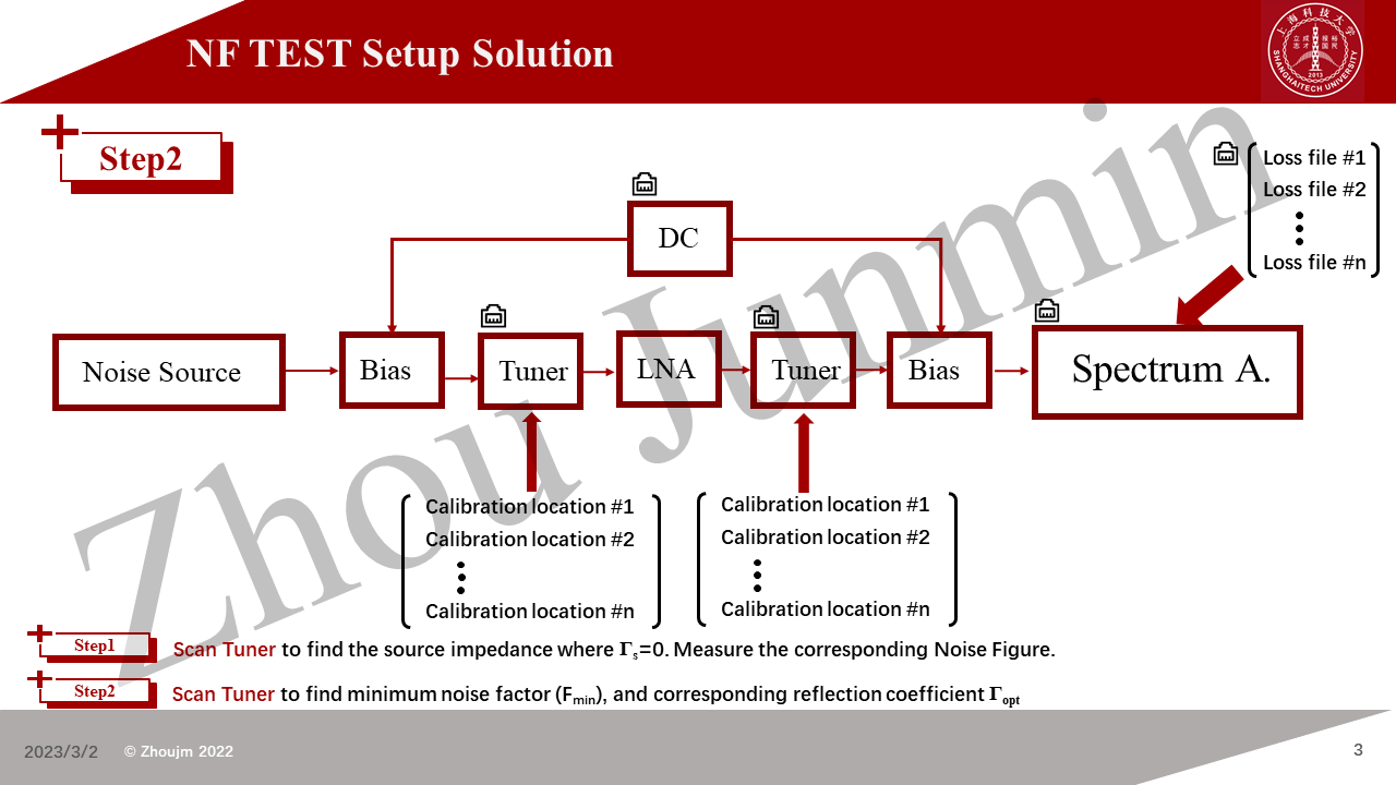
In this technique blog, I would like to introduce a solution set which could perform accurate NF measurement on the integrated LNA chips (DFT Chips) or a single FET. The software solution was uploaded on the Github (an auto-test solution based on python/NI Visa/PYQT5).
This measurement system is based on the Focus microwave impedance tuner, R&S ZNA43 vector network analyzer, R&S smart noise source, R&S spectrum analyzer (K30 kit: Noise Mode), .etc.


This blog takes the aggrement of CC BY-SA 4.0 , If you need to quote the work, please indicate the source